So there is this controversy of sorts… well not really for many of us, but certainly for some of us. See, the argument is that USB cables cannot and will not change the sound since it is just passing along 1's and 0's from point A to point B. It is all digital and so there you go. Nothing more, nothing less. But, many people beg to differ as there is more going on than just that and for sure we hear a difference between and among USB cables. So I asked a few cable designers what they thought was happening in a USB cable to cause these differences, or improvements over say a generic USB cable, and here are the results…
David Salz, Wireworld
Are USB cables really just 1's and 0's traveling down a wire? If not then what? Digital signals are actually square waves that are detected by the receiver when they pass a voltage threshold. Any variation in the shape or timing of these waveforms can cause errors in these signals.
How sending a file of music is different than that of an image to print? It is just data after all. When a file is saved or sent to a printer, the error correction system in the receiving device can ask the sending device to resend the file until it confirms that the file is completely correct.
Streamed music signals do not benefit from this resend function and therefore error correction systems cannot replace missing or corrupted data.
What is happening inside a USB cable that could impact the sound or information being transmitted? The normal losses of cables will round and tilt the signal waveforms, creating data errors that cause audible losses, tonal coloration and distortion. Those losses and colorations can easily be heard when standard USB cables are compared to reference adapters made from USB plug contacts soldered back-to-back. Designing a USB cable for minimal loss and maximum waveform fidelity is the only way to minimize these losses.
Separate power and signal? Computer power supplies are notoriously noisy and that noise can compromise the fidelity of USB audio. Most USB cables do not isolate the noisy power conductor from the signal conductors, so noise can mix with the signal and it can also enter the DAC through the 5 volt USB power conductor. Therefore, the 5 volt conductor needs to be isolated from the signal and filtered of noise or replaced by a separate quiet power source.
Noise? Noise can also be generated from static charge interaction within the cable. This triboelectric noise adds roughness to the signal waveforms. That roughness creates additional timing errors (jitter) in the signal. Reducing this noise enables cables to sound closer to the purity of the reference direct connection.
AQVOX
In past years I had very interesting conversations with a leading engineer of a really big cable maker, the German LEONI Group (70.000 employees 4bln turnover) , where we exchanged our experiences in the development of USB cables. From first contact on, albeit he is not an audiophile, but agreed that a USB cable must have effect on the sound quality. Because he experienced how many cable construction details have effect on the USB-signal stream. I know they are testing USB cables with logic analyzers for data integrity and visually with e.g. TEKTRONICS Digital-Phosphor-Oscilloscope DPO7000C with USB-option for about 30k USD or the Lecroy QPHY USB for correct "eye pattern" and frame transmission. This is required for USB certification. This equipment is fine for e.g. testing for Class2.0 maximum speed, but the scopes have no settings to be used for testing the performance in the far lower bandwidth of USB audio. This explains for example our finding that the audiophile quality of a USB cable does not correlate with the cables ability to transfer data at maximum rates.
Marcin Ostapowicz, JPLAY
1's and 0's are logical interpretations of voltage signals. USB signals are transmitted using differential signaling: for USB 2.0 signal levels are −10–10mV for logical low and 360–440mV for logical high level. So basically we are dealing with a very sensitive electrical (analog!) signal. High data rates of USB 2.0 result in jitter and attenuation becoming a major problem (higher frequencies attenuate faster than lower frequencies over distance. Additionally, higher frequencies are more susceptible to jitter). Degradation in the signal can be seen as it travels from a transmitter (PC) to a receiver (USB input in DAC). Reflections and clock inaccuracies cause jitter which closes the so called eye-pattern and makes the signal less readable. Music playback is a real-time process where accurate timing is everything, so it is extremely important to minimize jitter. We use these techniques in our cables to maintain signal integrity:
1) Reduce the capacitive reactance and inductive reactance to make the signal impedance reduce more accurately.
2) Considering the skin effect we only use very slim conductors.
3) We use triple shielding to prevent EMI. CPU speeds in PCs are up to few Gigahertz. It will emit a lot of electromagnetic radiation that's within the frequency range of USB signal.
In our top USB cable we also introduced a dual-lead design that separates the USB data lines from the power line. Each line has a separate USB type A connector with the dual lines terminated with a single USB type B connector. That plus double-shielded solid aluminum connectors results in better sound quality and a lower noise floor.
Jim Aud, Purist Audio Design
When thinking about a digital signal over USB, it can seem natural to think of it as a straightforward expression of 1's and 0's. However, it is more nuanced than that. Below a certain voltage, the signal says: "this is a 0." Above a certain voltage, it says "this is a 1." So, a 1 may be a 3.2 volt signal, and a 0 might be a 2.9. Since data transfer happens fast and often, it doesn't take much to skew a 1 to a 0, or a 0 to a 1. The digital signal isn't this series of neatly packaged squares, all labeled 1 or 0. They are in the ballpark, but they aren't completely uniform.
In an environment like that, interference is a factor. Things like EMI and magnetic fields come into play; anything that affects that signal can cause signal deformation. Imagine a cell phone next to a computer. That beeping and scratching noise is like the interference you can get along your cable. Shielding, quality of materials, even filtering on a USB cable can help prevent that interference, and make signal degradation less likely.
Length can be an issue. The longer the USB cable, the greater the chance of signal degradation through the resistance of the wire. This is why many manufacturers are switching to better, more high-quality conductors. Just for reference, the USB 2.0 spec limits the length of USB cables to 5 meters, while the USB 3.0 spec suggests 3 meters. Quality conductors mean you get the full benefit of that 3 meter, or 5 meter. You just get a better signal, whereas with a lesser quality conductor, the signal may begin to degrade earlier.
But what about error-checking? USB digital audio signal is on its own. Printing a document or image receives error checking. When sending a document or image to print, there's a code that tells the receiver how big the packet was. The receiver can check that code against the file received. With audio over USB, this technology is not there at this time. There's no checking the integrity of that file you just sent. This is because USB is an open-ended type of cable. It's like taking water and pouring it down a hose. You basically shoot stuff down the USB cable. There's no bit checking, sum checking, or other safeties like there are with HDMI, or with print data. Is what you send what you get? You have no idea.
The greater the frequency range, the more potential there is for error. A USB cable carries data through the megahertz range. Things that affect the signal at high and low frequencies, it's a whole different game. Things like skin effect and reflections really come into play. EMI reduction plays into the quality of the cable as well.
What you can do though, is get a good quality cable. Look for one with good filtering and low-resistance conductors. A separate power and data for the USB, something many manufacturers are experimenting with, is a good idea. Check the specification of your cable (is it USB 2.0 or 3.0?) and make sure you're within the required length. A quality cable ensures a clean, clear signal with no lost or altered packets—just like the artist intended. It can significantly reduce or eliminate outside interference—the type of interference that can result in errors. USB cables are an integral part of high-resolution computer audio systems, and a quality cable can deliver listening pleasure.
Mark Coles, Sablon Audio
Are USB cables really just 1's and 0's traveling down a wire? If not then what?
From a data transmission perspective, yes, however that is also the case with S/PDIF cables and the notion of them not mattering has been debunked decades ago. Audiophiles should try take as much care in the selection of their digital cables (both USB and Ethernet) as they do with their analogue signal cables and power cords.
How sending a file of music is different than that of an image to print? It is just data after all.
They are technically the same however music is life and death to some audiophiles and much more important to others.
What is happening inside a USB cable that could impact the sound or information being transmitted?
From a design perspective, closely targeting 90ohm impedance (rather than the broad +/- 10% the specification allows) and controlling noise are core building blocks. From an implementation perspective however, the careful selection of good sounding conductors can elevate performance to a rather higher level.
Separate power and signal?
Separation can be achieved though both physical separation and also electrically, via shielding. I use both methods.
Noise? Jitter? Timing?
To my mind, noise and jitter are closely related and equally undesirable. Consideration should also be given to the USB transmitter / receiver modules which may have been built down to a price rather than to a standard.
Is it really a digital signal or an electrical signal?
Is an electrical signal with two states, 0 and 1.
Alex Sventitsky, WyWires
Why USB cables improve audio performance.
Digital interfaces in general and USB cables in particular cause angst among many audiophiles since it is very unclear how such cables can affect or improve audio performance in a home stereo system.
Many argue that digital cables do nothing but transmit "ones" and "zero's" therefore there can be no audible difference among different cables. Audiophiles who have sampled different USB cables will often state that yes, USB cables do indeed sound different. As I read through social media discussions about cables, nothing causes more rude and obnoxious behavior than arguments about USB cables sounding different, or not.
What is a "one" and what is a "zero" anyway? One's and zero's are binary data, sometimes referred to as "machine language" where a "one" is "on" and a "zero" is "off" if you imagine a light switch. Strings of ones and zero's are useful in creating coded representations of human recognizable information that a machine is able to utilize using nothing but on and off conditions inside of its circuitry.
A USB host (your computer or music server) sends packets of one's and zero's in a predetermined format to your DAC, which then converts these packets to an analog signal that represents the music content (human recognizable information) that originated on your computer's hard drive as coded one's and zero's.
The USB Standards Document is 650 pages long and mind numbingly complex. I'll try to boil it down to the salient points that relate specifically to cable issues.
There is no such thing as a purely digital signal. Digital "data" is represented by electrical signals that meet certain conditions. In the case of USB cables, these conditions are robustly defined in the USB Standards Document. The data transfer within a USB cable is accomplished by using two electrical conductors, D+ and D-. USB defines one's and zero's as a difference between the two electrical signals transmitted by D+ and D-. A One is when the D+ signal is 200 millivolts greater than the D-signal. A Zero is when the D+ signal is 200 millivolts LESS than the D- signal.
A string of voltage differences or one's and zero's is defined as a "packet" and is asynchronous, meaning once a packet is sent, the host waits for confirmation of receipt before sending the second and the third, etc.
Your host device (the USB transceiver inside your computer) sends the appropriate voltages via D+ and D- at a frequency of between 1.5 to 480 megabits per second through the USB cable to the DAC and this is how it all works in VERY simple terms. Sorry engineers, I didn't write this for you so don't bore us with snarky comments.
USB cables transmit electrical signals as do analog cables but at a much higher frequency (up to 480 MHz). Like all electrical conductors, the integrity of the transmitted signal is dependent upon the basic electrical parameters of Inductance (L), Capacitance (C), Impedance (R) and Crosstalk.
The job of a cable designer is to minimize the potential harm caused to the electrical signal by the deleterious effects of L, C, R and Crosstalk. Inductance is a phenomenon where as current travels through a conductor, eddy currents are formed that try to push voltage in the opposite direction of the flow of the signal. Capacitance is when as the signal travels, some of the energy escapes from the conductor and is briefly stored in the material adjacent to the conductor and then dissipated back into the conductor. Impedance or resistance is where voltage may drop over a given length of the conductor due to insufficient cross sectional area of conductor material being used for a specific application. Crosstalk is the movement of energy from one conductor to the one adjacent. All four of these phenomena cause "jitter" which is a defect in the precise timing of data that is required to maintain the integrity of the data that is being streamed to the DAC, with crosstalk and capacitance being the biggest culprits in my opinion. The 650 page USB Standards document provides guidance dealing with impedance and crosstalk but they ignore Inductance and Capacitance completely. Unfortunately the USB Standards Board focuses exclusively on USB as a file transfer facility and not a facility for real time streaming of audio and video.
Another aspect of USB cables is the transmission of power from the host to unpowered USB devices. The 5V power legs within a USB cable can also cause problems with the integrity of the D+ and D- signals if not properly isolated.
Finally, external phenomena such as Radio Frequency Interference (RFI) and Electro-Magnetic Interference (EMI) can introduce unwanted effects that will corrupt USB signals. Indeed, the USB specification for USB1.1 and greater requires an RFI/EMI shield to be electrically connected to the USB housings at either end of the cable. USB 2.0 firmware will verify the existence of electrical continuity between the A and B housings as part of the handshake process.
At WyWires, we have been making USB cables for some time and have learned much about how electrical parameters affect the performance of our cables. We have selected conductor materials, dielectric materials, shielding materials and assembly processes that minimize as much as possible all of the factors that can harm the critical differential voltage differences between the D+ and D- conductors. Our conductor materials are copper Litz wire with very fine strands of individually insulated copper that virtually eliminates eddy currents thus minimize inductance. The dielectric materials we use include cotton and air, resulting in very low capacitance. Our D+ and D- conductors are separated from the RFI/EMI shield with a layer of air and a PTFE Teflon tube. The RFI/EMI shield material isolates the data and power legs. In our Platinum series USB cable, there are two additional layers of RFI/EMI shielding, one layer of heavy, densely braided copper and a layer of metalized Mylar, which is more effective than copper for draining away very high frequency RFI.
Paying close attention to the electrical performance of cables has yielded a USB interface that vastly outperforms any generic printer cable and anyone can hear the improvements immediately. Dynamics, accurate tone, complete dimensional information and precise instrument localization and more are what you'll experience with our USB cable. The differences are not subtle.
George Cardas, Cardas Audio
USB cables make a difference in part because the stock ones cut too many corners to save a penny.
The lack of isolation between the digital and the power is criminal. This oversight creates noise of several types.
As to the digital—its ones, zeros, and time—the problem here is multi-faceted but basically the cables are not true transmission lines because the dielectric constant is variable and more than "1". This results in a nonlinear propagation rate because the amount of dielectric retention is proportional to Dwell (the number of ones in a row) so unless you match the propagation in the conductor to the dielectric you will have a variable arrival time at the far end of the cable—now this is jitter and it effects the timing of audio signal this a key part of digititis—etc. We are unbelievably sensitive to errors in timing.
Sending the file is in fact the same as sending a photo—the difference is that a photo is fixed in time when you play it back—audio is not... it's all about time not the data
Materials are relevant in that they should be pure and consistent—dielectrics are relevant but more with respect to matching their dielectric constant with the conductor than which one you choose—I prefer PFA because of its good dissipation factor. As far a Metals are concerned as long as they are pure and soft, the difference between silver and copper is not as important as the geometry of the stranding IMHO—and I make most of the silver used in the industry today.
Joe Cohen, Lotus Design Group
The answer is simple: Digital cables are analog cables. They are subject to all of the environmental issues that any interconnect or phono cable, for that matter, is subject to. The choice of materials and architecture of a cable will influence how it behaves in the face of internally and externally generated noise. The ideal digital cable will be entirely free from the effects of such noise. The very high frequencies generated in the digital milieu will penetrate commonly implemented defenses and heroic measures are required to overcome them.
Joe Reynolds, Nordost
There are many factors to consider when designing a high performance USB cable. In order to get optimum performance it is necessary to reduce noise, crosstalk, and jitter in the cable. In order to do this a number of factors need to be considered. Timing errors which can be measured in a cable cause audible effects which can heard in an audio system. The digital signal which is expressed as a square wave needs to arrive from the source to the DAC as squarely as possible. If the bandwidth of the cable is not sufficient or if there is noise on the signal the square wave will be sloped at the edges and not sharp and clean. This can cause problems for the decoding circuitry of the DAC which is manifested as audible defects in musical performance.
The most important factor in USB cable design is precise geometrical accuracy in conductor layout. The precision of insulation extrusion and consistency in the manufacturing process have a huge bearing on improving the electrical performance of the cable.
The type of insulation material used has also big effect on the signal attenuation of the cable. That is the loss of signal over distance. This is affected by the material used to insulate the conductors. Many of the cheaper plastics used in mass market cables have a high capacitance which tend to absorbs the signal quickly over distance. The best manufacturing method is to use a low capacitance material such as FEP (fluorinated ethylene propylene) insulation. Or as used on our higher end USB cables, Nordost's proprietary Micro-Mono Filament technology. This technology provides a minimal contact point between the insulation and the signal carrying conductor. This is done by winding a fine FEP thread around the cable in a helix effectively suspending the conductor in air while improving mechanical damping. This increases signal speed and gets rid of the timing errors which degrade sound.
Effective shielding which prevents noise from entering the signal path is vital to USB cable performance. It is also important to keep the power cables shielded from the signal carrying cables. We do this by double shielding the conductors with a silver plated braid and a separate foil shield.
USB cable performance is very much determined by the quality of connector termination. Cheap moulded connectors can compromise cable performance if care is not taken during the moulding process to prevent plastic leaking around the termination points. The best solution which we use is to hand terminate the USB cable using fully shielded, full metal jacket connectors with excellent strain relief. This guarantees a reliable high quality performance and excellent connection integrity.
Nordost is an American manufacturing company that has been in business for over 25 years. Its products are exported to over 60 countries. It produces multiple lines of high performance audio video, HDMI, 4K UHD, and Pro Sound cables as well as QRT power distribution products and resonance control devices in Holliston, Massachusetts. All of their products are fully manufactured in the USA.
John McDonald, Audience
As timing is a part of the music it is also integral to the timely conveyance of digital information. At CD quality there are 705,600 bits per second per channel transferring in a serial manner. The object of a high performance digital cable is to provide a pathway to deliver such data with as little change as possible. Just like the analog domain, for the timely conveyance of energy—micro-phonics, eddy current, dielectric losses, RF interference and impedance all play a role as considerations in optimal cable design.
Rob Woodland, Curious Cables
I come to uUSB cable design from a different perspective to many designers. I'm not a digital engineer. I'm an audiophile with experience in designing and manufacturing high-end connectors.
I spent time researching USB theory and evaluated the best USB cable products from leading manufacturers. I came to the conclusion that a "text book" USB cable design may be suitable for high speed data applications, but perhaps not that relevant when it comes to transmission of music files.
The best explanation is provided by Charlie Hansen from Ayre Acoustics. He describes the digital signal as a voltage or "electrical pulse" representation of 1's and 0's—so in effect an analog signal.
So, the first step is to view the USB cable as an analog cable rather than digital. In this sense, the closest analog relative is a "balanced" interconnect cable. Both feature differential mode transmission.
How sending a file of music is different than that of an image to print? It is just data after all.
They may not be all that different! It's just that we audiophiles with our discerning hearing can detect subtle differences between cables when listening to music.
There may be "printing-philes" out there who can discern differences between print jobs when using audiophile cables. Now there's an exciting pursuit!
What is happening inside a USB cable that could impact the sound or information being transmitted?
This is the big question. And the answer is "everything." Computer Audio is a warzone—starting with the hostile environment of a computer/server ending with a bombardment of EMI/RFI during USB transmission. Noise and more noise!
Internally, the 5V power leg and Ground can also transmit noise to the data lines. How you address this is the difference between many designs.
The physical relationship between the ground and data lines is important.
Insulation materials can store and release electrical energy, and affect propagation of the signal.
The USB connector itself needs to be considered.
Separate power and signal?
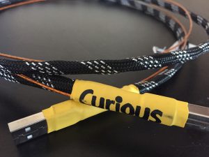
This is an obvious answer to the question of noise on the 5V leg. Get this wire away from the data lines—and shield it to prevent transmission of noise. The Curious uses a well shielded mini coax. It works extremely well.
If you want to go into materials that is fine.
Every element of the USB cable design needs to be taken into consideration, if the pursuit of excellence in sound quality is an objective.
As a designer, you start with the basics—choice of conductor material for the data lines. And all conductors sound different. Copper or silver? Stranded, litz or solid-core? What AWG? Listening tests are essential.
Conductor insulation or dielectric needs to be considered. What sounds best?
You then move to the ground and 5V power conductors. And the implementation of these wires.
Gavin Fish, Light Harmonic
There's a common misconception that DACs and digital cables have an easy job—all they have to do is tell if a signal is a one or a zero, right? It's not that quite that simple. In wide-bandwidth data applications, the ones and zeroes have to be bundled up into packets, and these packets are passed at blindingly high frequencies through send/receive chipsets and across cabling. Every small impedance mismatch, and every bit of power supply noise that travels along with the data… in our case, music, creates errors that can cause audible problems.
Conclusion... of Sorts
So what do we have then: Noise issues. Impedance issues. Timing issues. Error issues. Issues. Interesting o see a common thread here. So a lot is going on… I hear differences among cables. Differences that are more about being different in specific areas than overall differences. That is while many cables sound really good at getting the music out, they do some things better or differently than other cables that do some things better or differently as well. Subtle thing's for sure. But things that matter. Of course you may still not hear a difference or find any differences to be moot, and that is fine, but there is more to a USB cable than meets the eye... or ear. Thoughts?

