

Step Four – Designing and Building the Crossover Plinths
Once I had finished with breadboarding the crossovers, it was time to decide upon a permanent plinth arrangement to mount the Duelund CAST tinned-copper components to.
My criteria for the plinths was that, firstly and most importantly to me, that the plinths plus their Duelund CAST tinned-copper crossover components must fit inside the available space of the high-frequency horn cabinets with a little room to spare. Secondarily, I wanted the plinths to be easily removable should I decide I want to use the crossovers external to the cabinets at some point in the future.
You can see a lot of beautiful examples of crossover plinths at the Duelund and Mundorf Fanatics group on Facebook, and some of the CNC'd plinths I viewed were truly spectacular. For a while I considered doing a CNC'd plinth because the examples were so beautiful, but doing so would have precluded me from using them inside the Altec cabinets due to space considerations, violating my prime directive.
Also, as another consideration, it occurred to me that high-tech looking CNC'd plinths would not really fit in cosmetically with the nearly six decades old vintage "Stokowski" Altec's appearance.
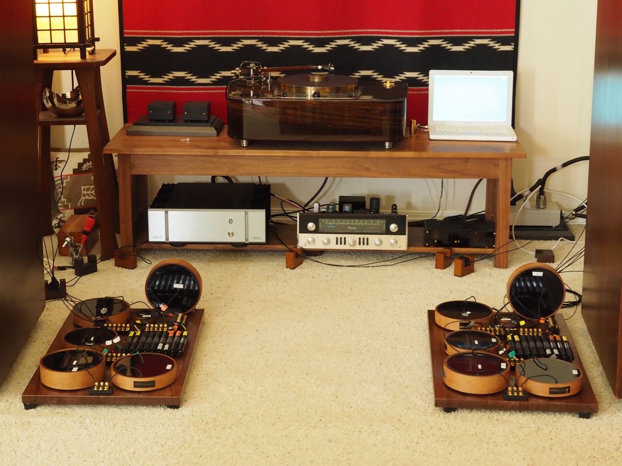
So, after considering what to do for a while, I finally settled on solid walnut plinth platforms, which are simple and attractive, and blend well the vintage Altec's appearance.
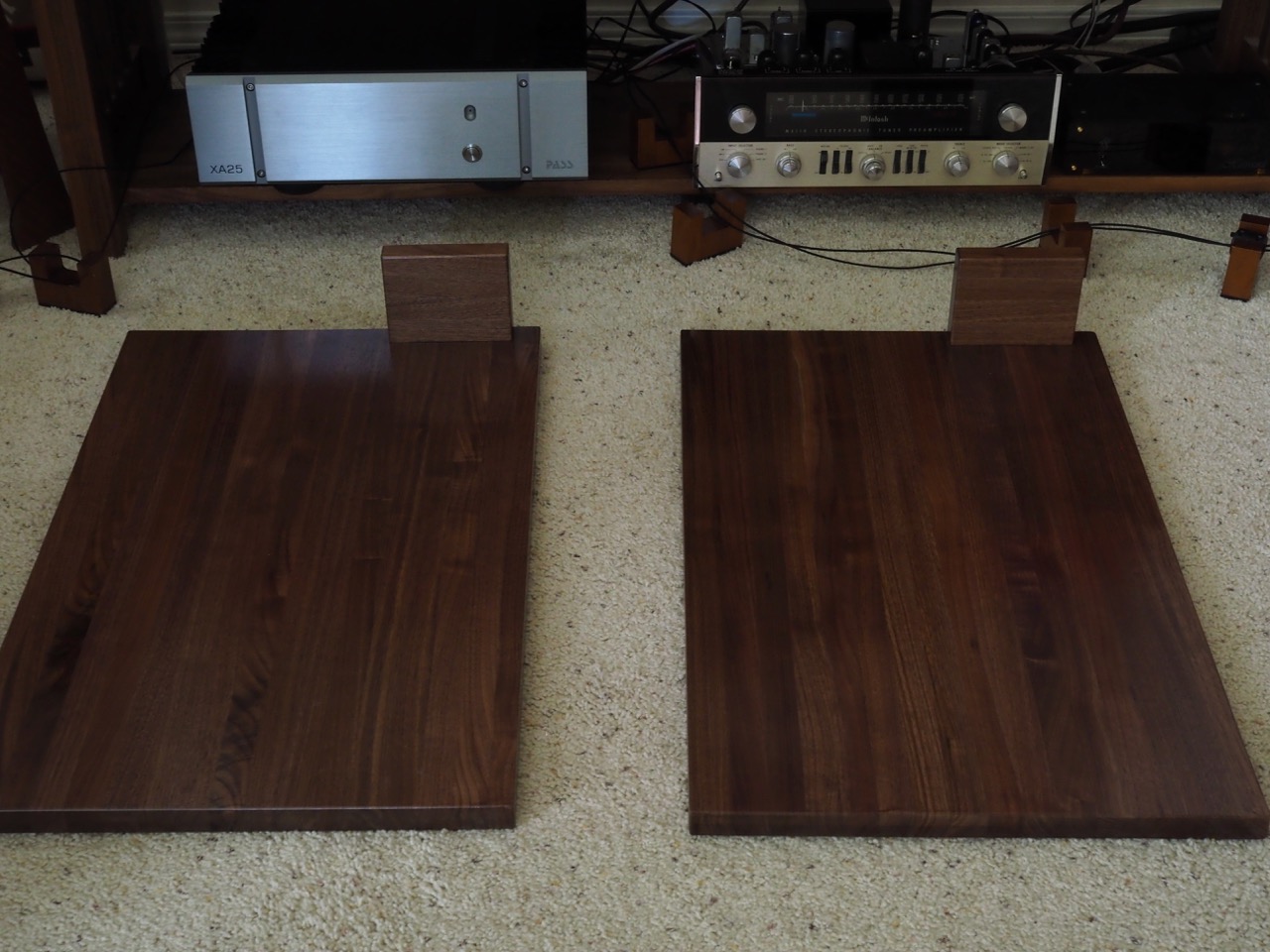
The Hardwood Lumber Company's Amish woodworkers built me a pair of 1-inch x 17-inches x 27-inches edge-grain butcher block style of walnut platforms to use as the base for the plinths, along with two matching 1-inch x 4-inch x 5-inch blocks that would serve as end pieces to mount the L2 6.6mH Duelund CAST tinned-copper inductors vertically with reference to the L3 6.6mH Duelund CAST tinned-copper inductors, to minimize the chance of any mutual inductance effects.
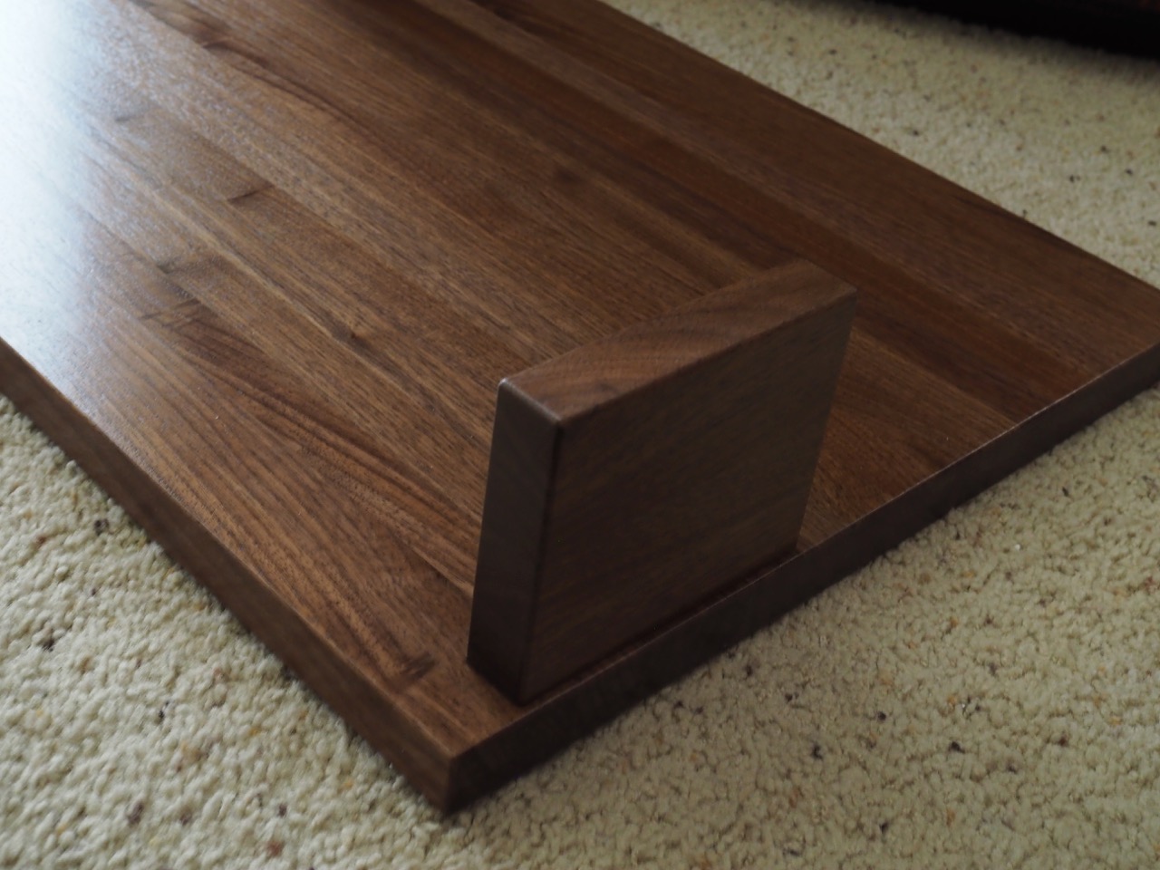
It took the Hardwood Lumber Company a little over a month to build the walnut plinth platforms and ship them to me. After they arrived, my buddy Dave Biancosino—an expert woodworker—drilled the bases & inductor mounting blocks, and secured them together with wood screws. Dave did a beautiful job on them – thank you, Dave!
Steps Five – Transfer Components from Breadboards to the Plinths and Finalize Positioning and Mounting
This step was a real chore, as it required completely disassembling the breadboard crossovers, and transferring each of the Duelund CAST tinned-copper components one-by-one to their new walnut plinth home.
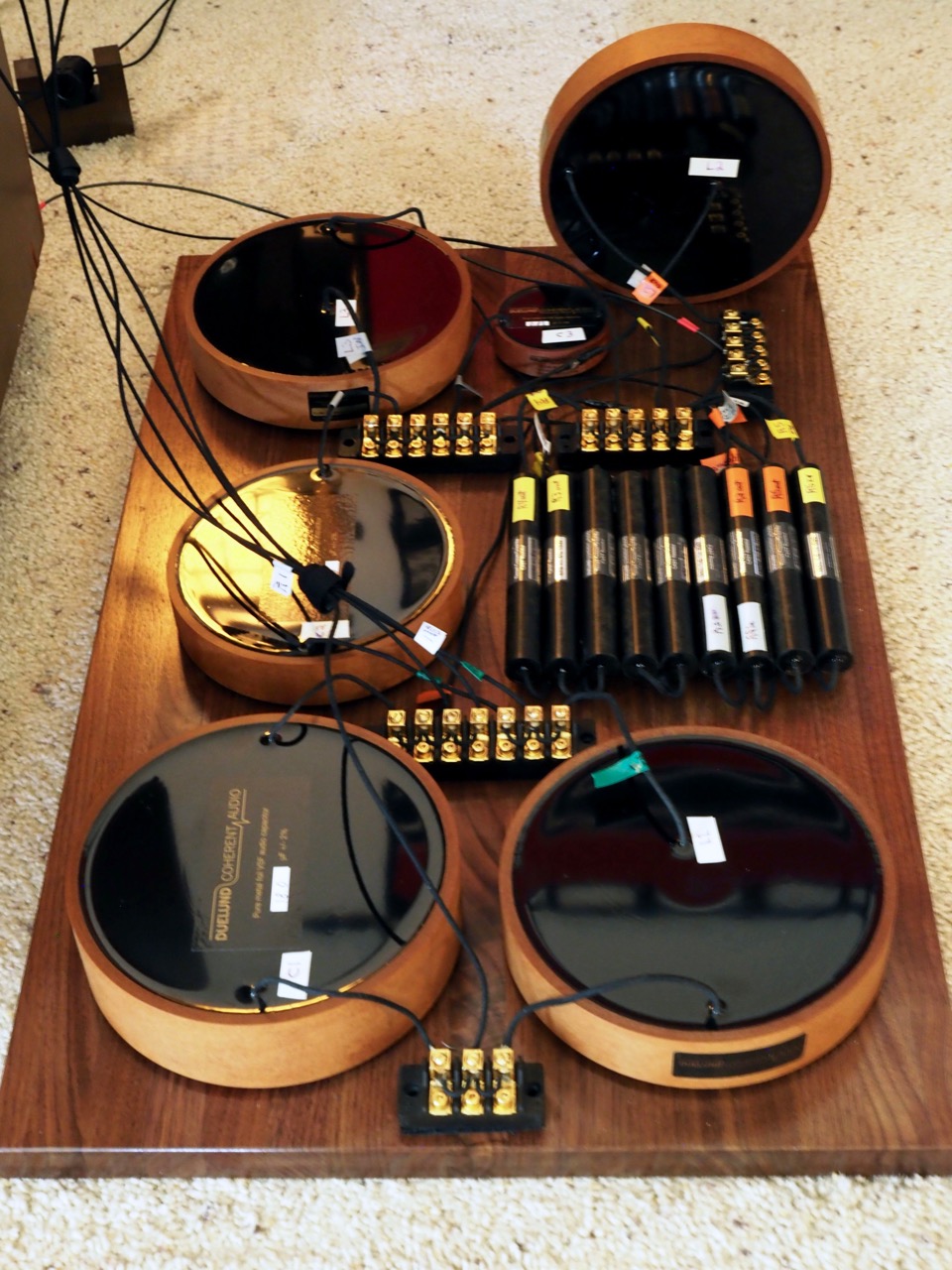
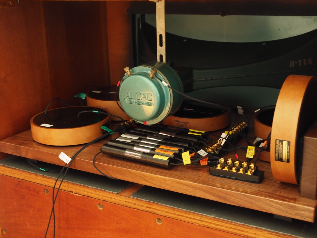
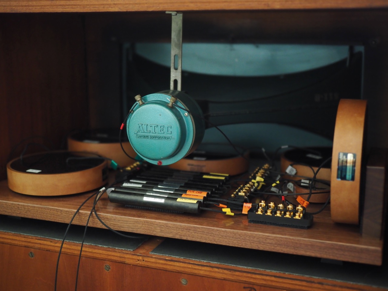
First, I placed the Duelund CAST tinned-copper components from the left crossover—along with the beautiful bespoke terminal strips that Santos Oropel (Troy Audio) provided for the Duelund-Altec Project (Thank you, Santos! More info on these HERE)—on the walnut plinth, and figured out the best places to position them.
Once I had positioning dialed-in, I then fixed all the components to the walnut plinths with VELCRO "Professional Grade Heavy Duty Industrial Fasteners" that are strength rated for up to 15-pound components, which is plenty even for the heaviest components in the project, the 6.6mH Duelund CAST Sn-Cu Air Core Inductor (7.18 pounds).
There's a couple of advantages of using the VELCRO to secure the components for this project. First, it makes the components easy to remove should the desire arise, and secondly, the hook and loop fastening system also adds a layer of decoupling of the components from the plinth bases. The VELCRO also makes the components look like they are "floating in the air" just above the surface plinth, which I think looks kind of cool!
The process was repeated for the right crossover.
Step Six – Wiring the Crossovers & Drivers
Next, I wired up all the crossover components with the Duelund DCA16GA tinned-copper wire, connecting them at the Troy Audio terminal strips.
To reiterate, the gorgeous gold terminal strips you see in the photos are courtesy of Santos Oropel (Troy Audio). These terminal strips clamp the wires directly together instead of using solder connections, which I think gives better sound quality, much like the McMaster Carr lugs I used for the Duelund-Westminster Project, but Santos' terminal strips are much more beautiful with their gold plating and CNC'd bases.
The wiring process was actually quite a chore and takes a while to do, as you have to cut each piece of wire to the correct length and strips the ends, and secure them in place.
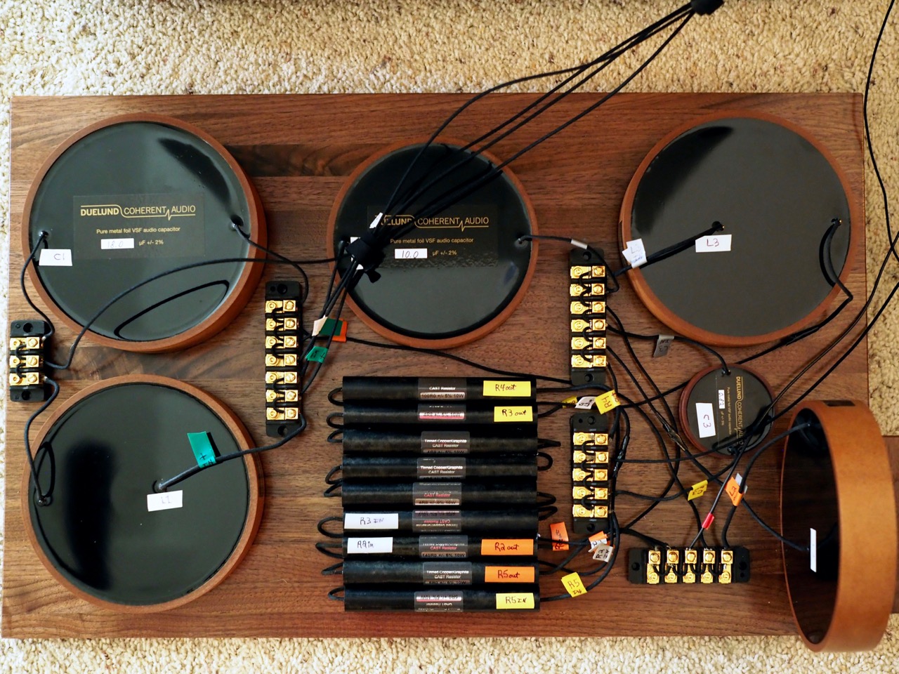
Look at the terminal strips, where each terminal screw lug is connected together by a short length of DCA16GA! Yeah, tedious, but worth it sonically.
Once I was finished wiring the crossovers, I connected them to the low-frequency Altec drivers with DCA16GA tinned-copper wire, connected the Altec high-frequency compression drivers to the crossovers with 600V DCA20GA, and then lastly connected the DCA16GA speaker cables to the crossovers.
Step Seven – Testing the Crossovers
This was—I hoped—the easy part, which just involved powering up the system and giving it a listen to make sure everything was working properly.
Everything worked perfectly, so I just sat back and enjoyed the fruit of my labors for a while, listening to music for the sheer pleasure of it!
Step Eight – Mounting the Completed Crossovers Back into the High-Frequency Cabinets
To prepare the high-frequency horn cabinets for installation of the crossovers, I first removed the binding posts, as they wouldn't be used, as I intended to connect the speaker cables directly to terminal strips in the crossovers.
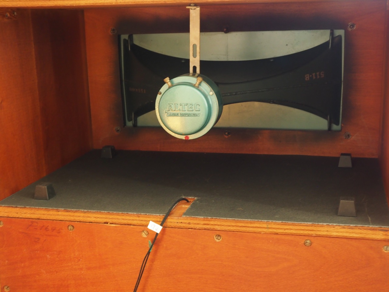
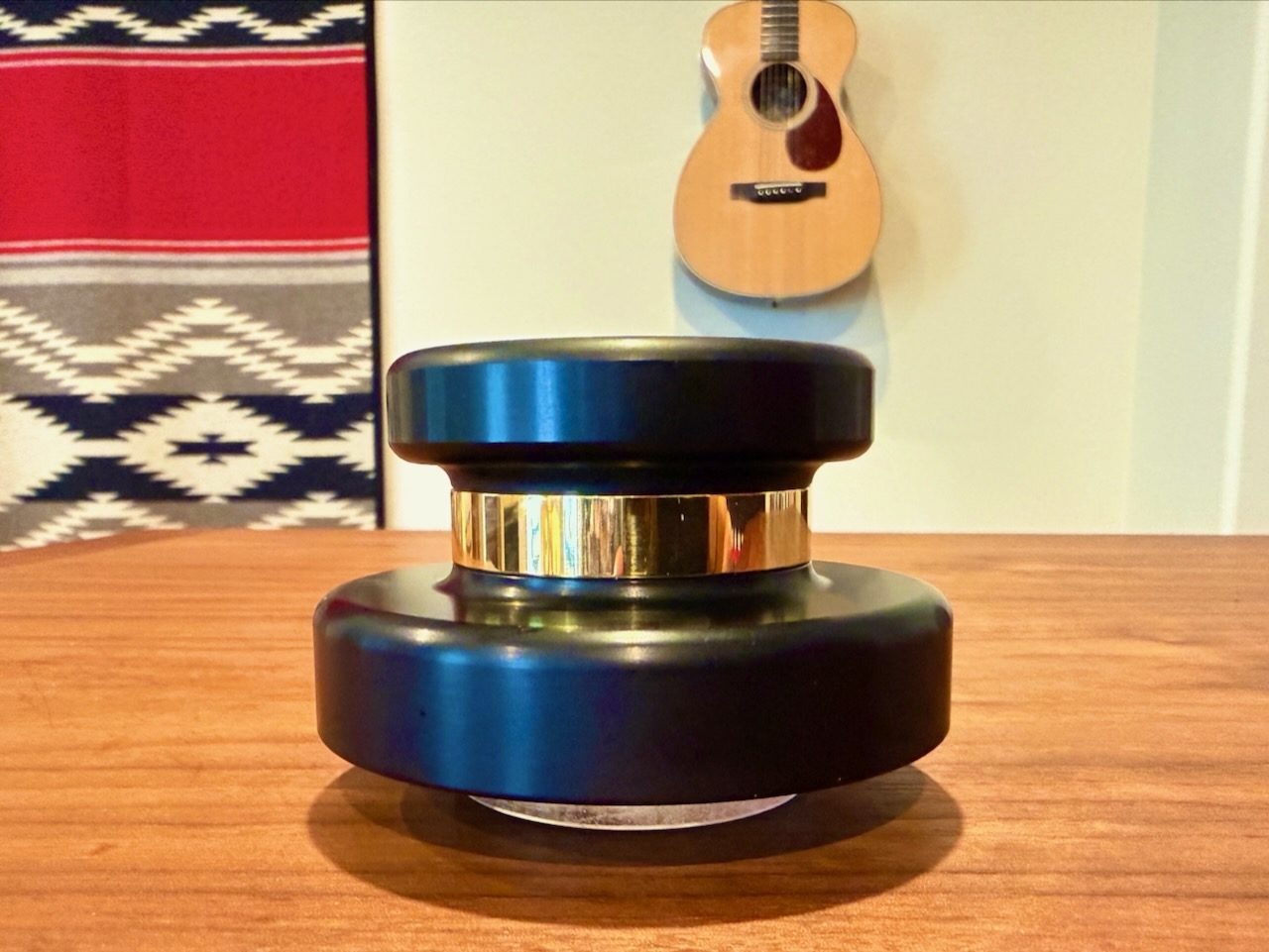
I then positioned the Herbie's Audio Lab Big-Tall & Extra-firm Tenderfoot isolation footers adhesive side down on the Soundcoat GPDS damping sheet to secure them in place (photo above).
My next step was to get my old power lifting belt out of the closet and put it on to protect my back, and then to lift the very heavy Duelund CAST tinned-copper crossovers up and into the high-frequency horn cabinets and position them upon the Herbie's isolation footers.
Once I had the crossovers positioned upon the Herbie's isolation footers so that they were not touching the cabinets' sides anywhere, I connected the drivers to the crossovers' terminal strips with Duelund DCA16GA (803B) / 600V DCA20GA (804A) tinned-copper wires, and then connected the DCA16GA speaker cables to the terminal strips. Done!
Step Nine – Celebrate the Results!
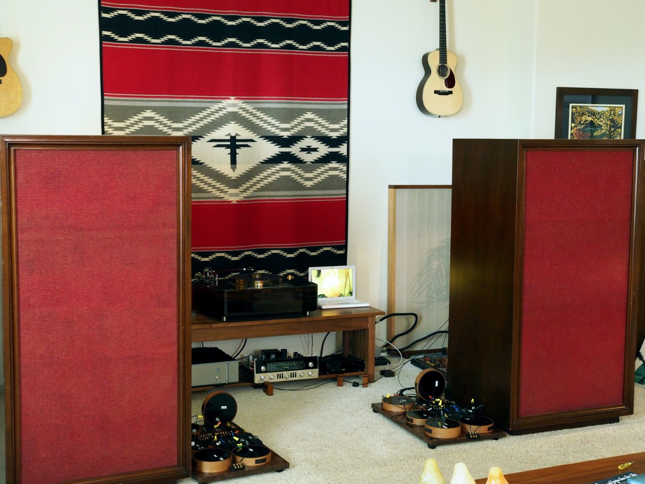
I powered up the electronics, then sat down to listen to make sure everything was working correctly in the crossovers—they were—and then I just sat there listening, and enjoying being mesmerized by the music playing—success!
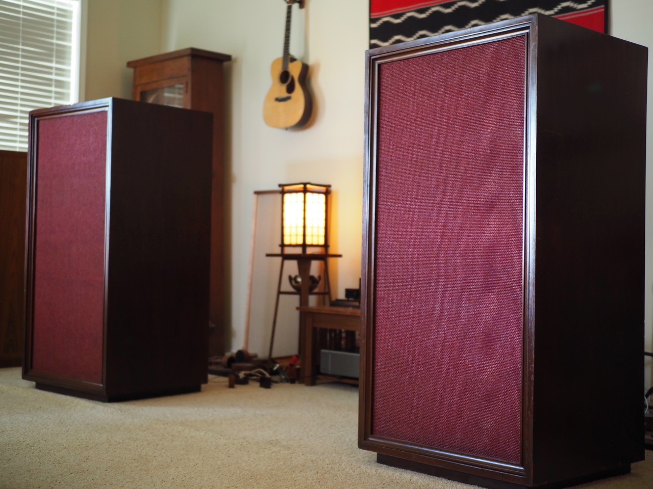
Leopold Stokowski's vintage Altec's have never sounded so good, I only wish the great conductor was still around to hear them—I think he would approve!